
How to Size a Valve Actuator
Use this valve actuator sizing checklist to record torque, thrust, duty, supply and mounting data. Complete the worksheet and send SHE your requirements.
How should a valve actuator be sized?
Valve actuator sizing starts with verified valve load data across the required travel, then checks whether the proposed actuator can deliver the necessary motion under the real operating conditions and duty. Record the valve type, medium, pressure, temperature, motion, opening and closing direction, torque or thrust profile, required operating time, movement frequency, mounting pattern, shaft or coupling dimensions, available supply, command signal, feedback and required response to loss of power or control. Do not select from nominal pipe size alone or apply an assumed universal safety factor: starting, running and seating loads may differ, while excessive output or incorrect torque settings can also damage or misoperate the valve. For a complete assembly, include valve materials and connection details. The final proposal should identify the actuator, valve where included, interface parts and control options, with current dimensions and wiring information checked before installation.
Start with the valve’s operating load across its travel, then check the actuator’s output, duty, mounting and control. Nominal pipe size alone is not enough to select an actuator.
1. Describe the valve and the process
Identify the valve type, medium, pressure, temperature and operating direction. State whether the movement is part-turn, multi-turn or linear. Request the valve manufacturer’s applicable torque or thrust information for the actual service conditions.
2. Review the load across the stroke
The load needed to start motion, continue travel and reach the required closed position may differ. Selection should address the relevant load profile rather than a single convenient number. Record the conditions under which the valve data was obtained and any project-specified sizing allowance.
3. Check duty and operating time
An actuator selected for occasional isolation is not automatically suitable for repeated positioning. Specify starts or movements per hour, expected cycle duration and the required operating time. Review the selected actuator’s duty definition, not simply its largest advertised output.
4. Match the installation
| Check | Record |
|---|---|
| Mechanical interface | Mounting pattern, shaft shape and dimensions, coupling and clearance. |
| Power or air supply | Available supply and the minimum conditions at the actuator. |
| Control | Command type, local/remote operation and required feedback. |
| Environment | Temperature, exposure and any required approvals. |
| Failure response | Required response to power, air or command-signal loss. |
5. Confirm the configuration before ordering
The proposal should identify the actuator, valve where included, interface components and control options. Request the relevant dimensions and wiring information before installation. Final commissioning and torque settings must follow the selected equipment’s instructions.
What to send SHE
Send the valve identification, available torque or thrust data, mounting details, supply, duty and control requirements. For a complete assembly, add medium, size, pressure, temperature and connection details. You can mark missing values as unknown.
Continue with electric valve actuators, compare on-off and modulating control, or request selection support.
Match the load check to the actuator mechanism
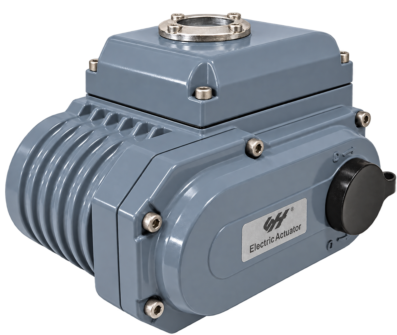
Part-turn electric actuation
For a rotary valve, compare the breakaway, running and end-of-travel torque with the actuator output for the proposed operating duty. Record the required rotation and opening time, as well as the electrical supply. A mounting flange match does not establish that the output shaft, drive insert or coupling is correct. Check the engagement depth and the space needed for manual operation.
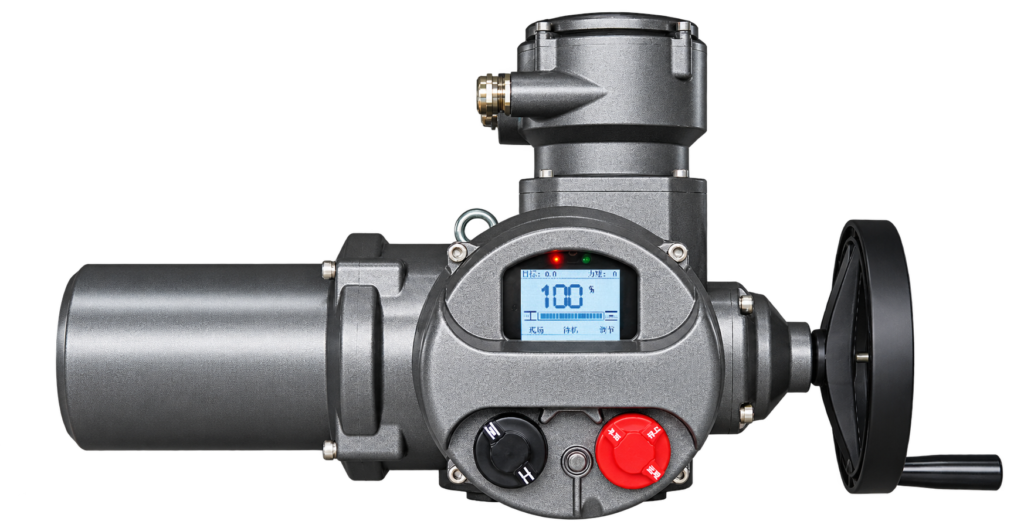
Multi-turn electric actuation
Specify the number of output turns and the required output speed. For a rising-stem valve, include stem diameter, thread details, thrust requirements and the clearance needed above the actuator. Identify whether the valve or the actuator assembly carries the thrust. Where a gearbox is used, provide its ratio, efficiency, permitted input load and output interface rather than comparing the valve load directly with the motor output.
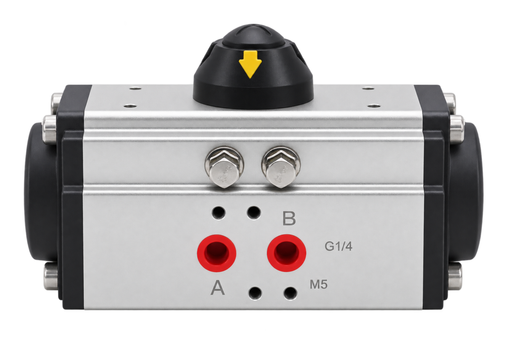
Pneumatic actuation
Use the minimum air pressure available at the actuator during movement, not only the compressor setting. For double-acting equipment, check output in both directions. For spring-return equipment, check the air stroke and spring stroke at the start and end of travel. The weakest point must still satisfy the applicable valve load and agreed sizing allowance.
Mechanical and control interface checklist
| Interface | Information to provide |
|---|---|
| Valve connection | Mounting drawing, shaft or stem dimensions, drive shape, engagement depth and alignment. |
| Supply | Voltage, phase and frequency, or minimum and maximum air pressure at the actuator. |
| Control accessories | Required solenoid, limit feedback, positioner, local controls and any separate control enclosure. |
| Environment | Ambient conditions, ingress protection requirement, corrosion exposure and any area classification. |
Compare the part-turn electric, multi-turn electric and pneumatic actuator families before requesting a configuration.
Valve actuator selection worksheet
Copy the fields below into your enquiry and attach the available valve data and drawings. Use the same operating conditions when comparing actuator proposals. Record values with units and a document reference; mark an unknown value as unknown so it can be clarified.
| Input | Information to record | Your value / document reference |
|---|---|---|
| Purchase scope | Actuator only, mounting kit or complete actuated valve; quantity and existing equipment to retain. | ________________ |
| Valve identification | Valve type, size, manufacturer or available identification, and connection designation. | ________________ |
| Process conditions | Medium, solids or contamination, normal and limiting pressure and temperature, and differential pressure. | ________________ |
| Valve load | Starting, running and seating torque or thrust through the relevant travel; conditions and source of the data. | ________________ |
| Allowable load and allowance | Valve or stem allowable loads and the agreed sizing allowance. Identify any project requirement. | ________________ |
| Movement | Part-turn angle, multi-turn total revolutions or linear stroke. Identify direction and end positions. | ________________ |
| Operating time | Required opening and closing time, or output speed and total turns where known. | ________________ |
| Operating duty | Isolation or modulation; starts or movements per hour, typical movement duration and operating pattern. | ________________ |
| Electric supply | Voltage, phase and frequency; identify the available supply at the installation. | ________________ |
| Pneumatic supply | Minimum pressure at the actuator during movement, maximum pressure, air quality and existing control equipment. | ________________ |
| Mechanical connection | Mounting pattern, shaft or stem dimensions, coupling, engagement depth and relevant assembly drawing. | ________________ |
| Command and feedback | Command type and range, required end-position or continuous feedback, and local or remote controls. | ________________ |
| Loss events and restoration | Required response to power, air and command loss separately; position, movement time, holding and restart requirements. | ________________ |
| Environment and clearance | Ambient conditions, exposure, required enclosure or area suitability, stem travel and maintenance access. | ________________ |
| Documents and verification | Requested load data, datasheet, dimensions, wiring or air circuit, applicable approval evidence and agreed functional checks. | ________________ |
For a replacement, include the old valve and actuator identification as well as the retained interface parts. A matching outline or nominal flange designation does not establish that the load, drive engagement, controls and operating duty are compatible. Identify each value that still needs confirmation before ordering.
Use a focused comparison before finalizing the package
- Still choosing the valve construction? Use the actuated ball valve versus butterfly valve checklist to compare process duty, materials, connection and the complete assembly.
- Defining pneumatic failure behavior? Read double-acting versus spring-return actuators and state loss of air, electrical power and command signal separately.
These comparisons help organize the enquiry; they do not replace the selected valve’s load information or the actuator’s applicable output and duty documentation. Keep the valve, actuator, mounting parts and controls on one configuration list so a change to any item can be reviewed.
General selection guidance. Confirm output, duty, interfaces and approvals against the current documentation for the proposed configuration.