
Double-Acting vs Spring-Return Actuators: Specify the Failure Response
Compare double-acting and spring-return actuators, define loss-of-air, power and signal responses, and prepare a complete pneumatic valve enquiry.
Published by SHE · 14 October 2026 · Pneumatic valve selection guide
A double-acting actuator uses compressed air for both travel directions; a spring-return actuator uses air for one stroke and springs for the return. Choose between them by defining the required valve response, checking the available output through each stroke, and reviewing the complete control circuit. The actuator name alone does not specify what happens after loss of air, electrical power or command signal.
This guide helps buyers turn “fail open,” “fail closed” or “stay put” into an enquiry that can be checked. It focuses on the complete pneumatic valve package rather than assigning a universal failure position to a product family.
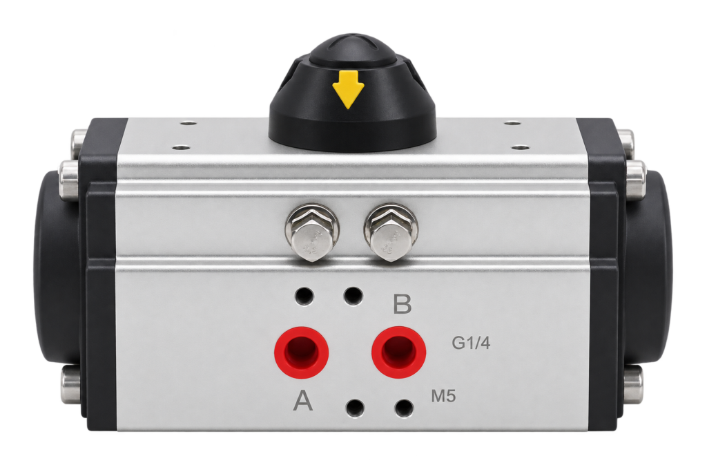
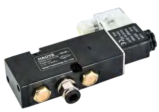
1. Compare the driving methods
In a double-acting arrangement, the control valve directs air to move the actuator in one direction and then reverses the air paths for the other direction. Both movements need a suitable pneumatic supply. Specify the opening and closing requirements separately, including the valve load and desired operating time.
In a spring-return arrangement, the air-driven stroke works against the springs. The springs provide the return movement when the air chamber can exhaust as intended. Confirm which valve position corresponds to the spring end of travel, and whether the spring output is sufficient throughout that movement.
| Check | Double-acting | Spring-return |
|---|---|---|
| Normal driving energy | Air pressure drives both directions. | Air drives one stroke; springs drive the return. |
| Output review | Check available torque through both pneumatic strokes. | Check both air-stroke and spring-stroke output for the chosen spring arrangement. |
| Failure objective | Define the required result and the circuit needed to achieve it. | Define the spring-end valve position and confirm that the circuit permits the required return. |
| Air control | Review both working paths, exhaust and any holding requirements. | Review supply, exhaust and any devices that could prevent the intended spring movement. |
| Purchase scope | Include the actuator, controls, interface parts and required documentation. | Include those items plus confirmation of the spring configuration and return duty. |
Compare complete configurations under the same operating conditions. An actuator-only quotation and a quotation including control accessories do not establish the same capability or installed scope.
2. Define three different loss events
“Failure” is too broad for a useful specification. Loss of plant air, loss of power to a solenoid coil and loss of the command signal are different events. A controller fault may leave the coil energized; a coil power failure may occur while air is still available. Write one requirement for each event before selecting hardware.
| Event to assess | Define the required outcome | Evidence to request |
|---|---|---|
| Loss or inadequate pressure of instrument air | Required valve position, starting position, permitted travel time and any required holding duration. | Air circuit, available stored energy if proposed, actuator output and exhaust path for this event. |
| Loss of electrical power | Identify the affected supply: solenoid, positioner or controller. State whether instrument air remains available. | De-energized control-valve state, coil arrangement, pneumatic connections and the resulting movement. |
| Loss or invalid command signal | Identify the failed signal and whether the receiving device remains powered. State the required response. | Controller or positioner configuration, command interpretation and the air-routing result. |
| Supply or signal restoration | Required restart behavior, permissives and whether automatic movement is permitted. | Documented restoration sequence and an agreed functional check. |
Record simultaneous losses separately where the application requires them. Define where air pressure is measured and how an invalid signal is identified. “Fail closed on loss of air” and “fail closed on loss of coil power with air available” should not be treated as interchangeable instructions.
3. Specify position, movement and holding separately
For a spring-return package, state the required spring-end valve position in words and identify it on the assembly drawing. Do not infer opening or closing from the direction of an indicator arrow alone. Valve orientation, coupling and the actuator arrangement must agree.
For a double-acting package, do not turn “no spring return” into an unsupported promise that the valve will remain locked indefinitely. Ask whether the proposal is intended to retain its position, continue a previous command or move using an additional energy source. State the required duration and allowable movement where holding is required.
Rotork’s Double-Acting Actuator Configurations illustrates distinct circuit arrangements for electrical and pneumatic supply loss, including differences between position retention and locking. These are reference arrangements for another manufacturer’s equipment, not evidence that a particular SHE package includes those functions.
Separate the final position from the journey to that position. Specify travel time and any restrictions on automatic motion. The required outcome should come from the process requirements; selecting a spring mechanism does not determine the appropriate process response.
4. Check output through both strokes
Provide the valve’s starting, running and seating load data for the proposed medium, differential pressure and temperature. Compare it with the actuator’s available output across the relevant travel. A single catalogue torque value is not enough to check every point of a spring-return movement.
Use the minimum air pressure available at the actuator during operation, with the proposed regulator, solenoid and piping in the circuit. For spring-return equipment, request output data for the actual spring arrangement and check the air stroke and spring stroke. For double-acting equipment, check both powered directions.
Agree the sizing allowance and confirm the valve’s allowable loads. Increasing actuator size or changing the spring arrangement can affect other parts of the proposal, so document the complete configuration. Use the actuator sizing checklist to collect load, duty and interface information.
5. Review the solenoid and supporting accessories
The pneumatic solenoid control valve connects the electrical command to the actuator’s air paths. Confirm its pneumatic function, supply and working ports, exhaust connections, energized state and de-energized state. A single-coil and a double-coil arrangement need their own response review; neither a connector photograph nor the word “solenoid” defines the complete logic.
Include any positioner, pilot equipment, air treatment, manual override, check or locking devices shown in the proposal. Identify whether each affects movement or only reports position. End-position feedback can report a state without creating the movement needed to reach it. For intermediate positioning, review on-off and modulating control as a separate duty decision.
Check operating time with the proposed air paths and exhaust equipment. State electrical supply, control signals, ambient conditions and installation requirements. Request the corresponding connection and configuration documents rather than assuming accessory compatibility from appearance.
6. Agree a practical verification record
Ask for a configuration list linking the valve, actuator, spring arrangement where applicable, mounting parts and accessories. The air-circuit drawing should identify ports and component states, and the wiring information should identify the relevant supplies and commands.
Agree a functional verification procedure appropriate to the equipment and application. It should distinguish normal opening and closing, the specified loss events and restoration. Record the initial valve position, conditions, resulting movement and observed feedback. Site checks must follow the selected equipment’s instructions and the site’s authorized procedure.
For general manufacturer background on different spring-return installation arrangements, see the Emerson Bettis RPX installation manual. Its equipment-specific instructions and ratings should not be transferred to a SHE assembly. Obtain the instructions applicable to the proposed configuration.
7. Send a complete enquiry to SHE
- Valve and duty: valve identification, medium, pressure, temperature, required travel and operating frequency.
- Load and interface: valve torque data, mounting drawing, drive dimensions and installation clearance.
- Air supply: minimum and maximum pressure at the actuator during movement, air quality and existing piping details.
- Three loss-event requirements: air loss, electrical power loss and command-signal loss, each with position, travel-time and holding requirements.
- Control configuration: electrical supplies, signals, solenoid or positioner information, feedback and any manual-operation requirements.
- Restoration and documents: restart requirements, proposed verification record, drawings and requested configuration documentation.
Start with the rack-and-pinion pneumatic actuator family and pneumatic actuator catalogue. If the energy source is still undecided, compare electric and pneumatic actuation before finalizing the control package.
Send Your Failure-Response Requirements
Frequently asked selection questions
Does spring return always mean fail closed?
No. Specify the required valve position and confirm the spring arrangement, coupling and control circuit. The complete assembly must be checked for the stated event.
Does double acting guarantee a locked last position?
No. Position retention, locking and holding duration require an explicit specification and a suitable documented circuit. Do not infer them from the actuator name.
Is loss of command the same as loss of solenoid power?
No. Identify which device loses its input, which supplies remain available and how the receiving device responds. Record these conditions in the failure-response worksheet.