
 Representative configuration
Valve Automation Accessories
Declutchable Manual Override Gearbox
A declutchable manual override gearbox provides a handwheel drive within a pneumatic valve assembly.
View Product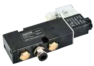
Representative configuration. Confirm the appearance and dimensions of the proposed model.
A pneumatic solenoid control valve routes instrument air in response to an electrical command.
Send your requirements for the proposed configuration.
A pneumatic solenoid control valve routes instrument air in response to an electrical command. In a valve-automation package it switches the air paths needed to drive the actuator, so port arrangement and de-energized behavior must match the actuator type.
Choose the pneumatic circuit from the actuator action and desired failure response, not from the appearance of the coil. Confirm the minimum operating pressure, required flow capacity and acceptable switching time. Exhaust restrictions and silencer selection affect stroke speed. Hazardous-area use requires a correctly approved coil and valve assembly with suitable installation components; no approval is inferred from a similar-looking enclosure.
Check both mechanical and control compatibility before installation. A matching exterior or similar part description does not confirm interchangeable ratings, porting or wiring.
On-off control of compatible double-acting or spring-return pneumatic valve actuators.
Identify the actuator or valve, mounting dimensions, control circuit and installation environment. Include the required electrical or pneumatic ratings, quantity and any documentation requirements.
Confirm the final assembly drawing, materials, ratings and control documentation for the proposed configuration before ordering. Product photographs show representative configurations.
Browse Valve Automation Accessories, use the actuator sizing checklist, or send your application requirements.
Need mounting dimensions? Request the drawing for your proposed configuration.
| Working medium | Suitable conditioned instrument air |
|---|---|
| Reference supply-pressure range | 0.15-0.8 MPa for the illustrated standard configurations |
| Reference ambient range | -10 to +60 degrees C; version dependent |
| Porting | Specify 3/2, 5/2 or other required circuit |
| Electrical supply | Specify coil AC/DC voltage and control arrangement |
| Interface | Air-port size, mounting pattern, exhaust and connector |
Confirm the final ratings and dimensions against the documentation for your selected model.
Request the current datasheet, dimensional drawing and wiring or air-circuit information for the proposed product or assembly. Include your valve type and supply requirements so the documents match the configuration under discussion.
Representative configurationA declutchable manual override gearbox provides a handwheel drive within a pneumatic valve assembly.
View Product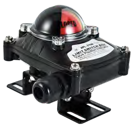 Representative configuration
A valve limit switch box reports one or more defined rotary positions to a control system.
View Product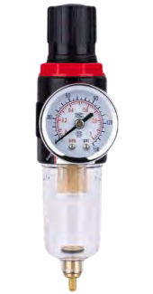 Representative configuration
An instrument-air filter regulator removes collected contamination and regulates the pressure supplied to pneumatic controls.
View ProductInclude the valve type, operating load, supply and control requirements.
Send your valve details and operating conditions to SHE.