
 Representative configuration
Pneumatic Ball Valves
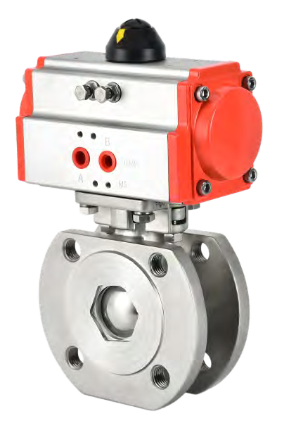
Pneumatic Thin-Pattern Ball Valve
A thin-pattern ball valve provides a compact face-to-face arrangement where available pipe length is limited.
View Product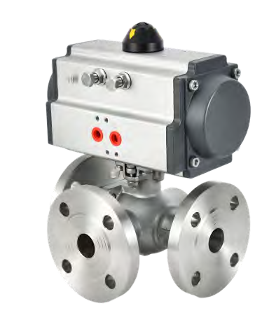
Representative configuration. Confirm the appearance and dimensions of the proposed model.
A pneumatic three-way ball valve switches or combines flow paths using a multi-port ball.
Send your requirements for the proposed configuration.
A pneumatic three-way ball valve switches or combines flow paths using a multi-port ball. L-port and T-port passages create different routing possibilities, and the port diagram must be defined before the actuator travel and end positions are selected.
Do not assume that every three-way valve provides a shut-off position or allows every port to act as the inlet. Seat arrangement, pressure direction and ball passage determine the permitted flow paths. Send a sketch showing the common port, the desired connected ports and any position that must block flow. Where a third intermediate position is needed, discuss a three-position actuator and the required control sequence.
Review supply pressure at the equipment while it is operating, not only the compressor setting. Select accessories and the loss-of-air response for the complete assembly.
Flow diversion, tank selection, bypass routing and compatible mixing circuits.
Include the medium, normal and maximum pressure and temperature, connection dimensions, required operating time and quantity. For an existing installation, add identification photographs and the current assembly drawing.
Confirm the final assembly drawing, materials, ratings and control documentation for the proposed configuration before ordering. Product photographs show representative configurations.
Browse Pneumatic Ball Valves, use the actuator sizing checklist, or send your application requirements.
Need mounting dimensions? Request the drawing for your proposed configuration.
| Flow pattern | L-port or T-port, specify routing diagram |
|---|---|
| Connection options | Flanged or threaded |
| Reference flanged pressure classes | PN16 or PN25 versions |
| Drive selection | Travel angle and stop positions matched to port map |
| Control | Solenoid operation with optional position indication |
| Critical enquiry input | Which ports connect in every commanded position |
Confirm the final ratings and dimensions against the documentation for your selected model.
Request the current datasheet, dimensional drawing and wiring or air-circuit information for the proposed product or assembly. Include your valve type and supply requirements so the documents match the configuration under discussion.
Representative configurationA thin-pattern ball valve provides a compact face-to-face arrangement where available pipe length is limited.
View Product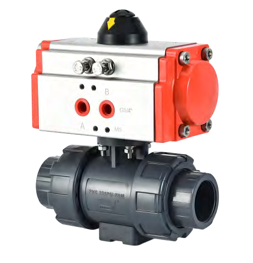 Representative configuration
A pneumatic PVC ball valve combines a plastic-bodied rotary valve with an air actuator.
View Product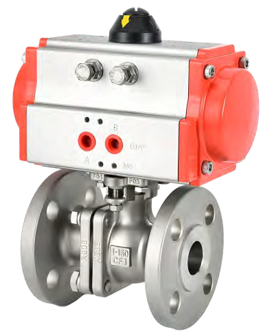 Representative configuration
A pneumatic flanged ball valve combines a rotary ball valve with an air actuator and mounting assembly.
View ProductInclude the valve type, operating load, supply and control requirements.
Send your valve details and operating conditions to SHE.