
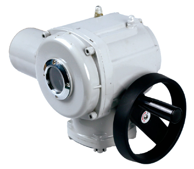
 Representative configuration
Part-Turn Electric Actuators
Industrial Part-Turn Electric Actuator
This industrial part-turn actuator is a rotary drive for ball valves, butterfly valves, dampers and similar limited-travel equipment.
View Product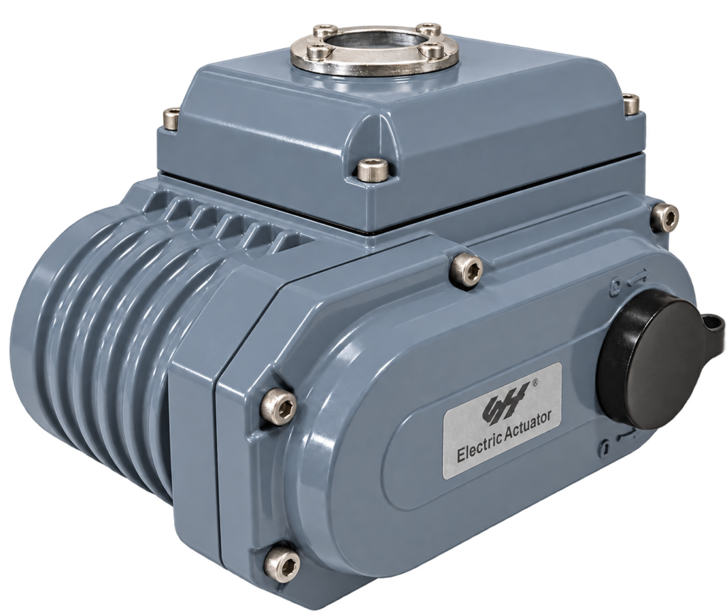
Representative configuration. Confirm the appearance and dimensions of the proposed model.
Electric actuation for part-turn valves, including ball and butterfly valve applications. Compare the valve load, travel, operating time and control duty before selecting a configuration.
Send your requirements for the proposed configuration.
A part-turn electric actuator converts electrical power into controlled rotary movement. It is used where the valve or damper needs a limited angle of travel rather than multiple output revolutions. Ball and butterfly valves are common applications, but the required travel and mounting arrangement must be checked for the actual valve.
The published range includes maximum output torque values from 50 to 2,600 Nm. The table below lists the corresponding operating time and motor power for reference. These values describe different configurations; they are not adjustable settings available on every actuator.
| Maximum output torque (Nm) | Operating time (s) | Motor power (W) |
|---|---|---|
| 50 | 30 | 10 |
| 100 | 30 | 20 |
| 150 | 30 | 20 |
| 200 | 30 | 40 |
| 300 | 30 | 45 |
| 400 | 30 | 60 |
| 600 | 30 | 90 |
| 1000 | 40 | 120 |
| 2000 | 40 | 130 |
| 2600 | 60 | 151 |
Use this table to identify a starting point for an enquiry. Confirm the final datasheet, travel angle, supply, duty and mounting dimensions for the proposed configuration. Motor power alone does not establish the valve load the actuator can handle.
Request the valve's starting, running and seating torque at the intended pressure, temperature and medium. The selected output and torque settings must meet the required load without exceeding the valve's allowable limits. Nominal pipe size alone is not a sizing method.
On-off service and repeated intermediate positioning create different operating demands. Include the supply voltage, phase and frequency, expected starts or movements per hour, command signal and required feedback. Define the response to power or signal loss; automatic return must be explicitly confirmed for the proposed arrangement.
Send the valve identification, load data, mounting drawing and installation environment with your enquiry. Where enclosure protection or hazardous-area approval is required, state the exact requirement and request applicable evidence for the selected unit. A photograph does not establish an approval or rating.
Review the actuator sizing checklist and on-off versus modulating control, or return to part-turn electric actuators. Ask for current dimensions and wiring information before installation.
The compact part-turn range includes different wiring and control arrangements. Identify the required function before requesting the electrical diagram; terminal assignments and supply details vary by configuration.
| Control version | Purpose and selection detail |
|---|---|
| AC on-off | Open/close operation with the specified single-phase or three-phase electrical supply. |
| DC on-off | Direct-current supply version with a matched connection and switching arrangement. |
| Position feedback | Potentiometer or specified feedback arrangement for remote position monitoring; confirm output and controller compatibility. |
| Modulating control | General or intelligent regulating configuration with a matched command input and position feedback. |
| Auxiliary contacts | End-position or additional switching contacts where included in the selected control package. |
Need mounting dimensions? Request the drawing for your proposed configuration.
| Motion | Part-turn rotary output |
|---|---|
| Reference maximum output torque | 50–2,600 Nm across the listed configurations |
| Reference operating time | 30–60 seconds, depending on configuration |
| Reference motor power | 10–151 W, matched to the listed output |
| Supply versions | AC or DC; specify voltage, phase and frequency |
| Control versions | On-off, position feedback or modulating, configuration dependent |
| Mechanical interface | Confirm mounting, shaft and coupling dimensions |
Confirm the final ratings and dimensions against the documentation for your selected model.
Request the current datasheet, dimensional drawing and wiring or air-circuit information for the proposed product or assembly. Include your valve type and supply requirements so the documents match the configuration under discussion.
Representative configurationThis industrial part-turn actuator is a rotary drive for ball valves, butterfly valves, dampers and similar limited-travel equipment.
View Product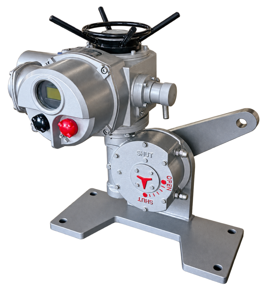 Representative configuration
A lever-arm electric actuator drives a damper or linked mechanism through a rotating arm and connecting linkage.
View Product Representative configuration
A geared quarter-turn actuator combines a multi-turn electric drive with a secondary reduction gearbox.
View ProductInclude the valve type, operating load, supply and control requirements.
Send your valve details and operating conditions to SHE.