
Electric Actuator Hunting: Six Causes and How to Diagnose Them
Electric actuator hunting can come from signal noise, PID tuning, valve gain or mechanical faults. Use this checklist to record symptoms and plan the check.
Published by SHE · 16 October 2026 · Electric actuator troubleshooting
Electric actuator hunting is repeated movement around a demanded position or process setpoint. Six possible causes are a fluctuating measurement, unsuitable PID tuning, excessive valve gain, mechanical play or friction, electrical interference, and an actuator stopping or feedback fault. Diagnose the signal path before changing settings: the actuator may be following an unstable command rather than creating the oscillation itself.
Persistent cycling increases operating demand on the motor, transmission and valve. It can also make flow, pressure or temperature control less consistent. A useful investigation separates the process-control loop from the actuator’s internal position-control loop, then establishes which signal or movement becomes unstable first.
Start by recording four trends together
Record the process setpoint, measured process variable, controller output and actual valve-position feedback on the same time base. Include relevant equipment starts, operating-mode changes and alarms. Note the oscillation period, its approximate amplitude, and whether it occurs throughout the travel or only near a particular position.
Distinguish measured feedback from independently observed valve movement. A fluctuating feedback signal does not necessarily mean that the valve is physically moving. Equally, movement of an actuator indicator does not by itself prove that a loose coupling is transmitting the same movement to the valve stem.
| Observation | Investigation focus | Useful record |
|---|---|---|
| Process measurement changes first | Process pulsation, measurement installation or transmitter configuration. | Raw and filtered measurement trends with operating conditions. |
| Command repeatedly reverses | Outer-loop tuning, disturbances and interaction with other loops. | Setpoint, process variable and controller output. |
| Command is steady but position cycles | Position feedback, local control settings, transmission or stopping behavior. | Demand and position feedback with independent movement observations. |
| Feedback changes without confirmed travel | Feedback sensor, connection, scaling or electrical interference. | Local indication, remote feedback and the relevant signal wiring. |
These patterns guide investigation; none proves a diagnosis by itself. Carry out any manual-mode or movement test under the site’s approved procedure. Electrical inspection and mechanical work require the applicable isolation arrangements and the selected equipment’s instructions.
1. A fluctuating measurement drives a fluctuating command
Some processes contain real pulsation. Reciprocating-compressor discharge pressure and certain level measurements are examples where the measured value may vary rapidly. The transmitter can pass that variation to the controller, which then continually changes its output and causes repeated actuator movements.
First determine whether the fluctuation represents a process change, a measurement-installation problem or signal noise. Compare the transmitter output with the controller’s received value. Review sensor location, impulse-line condition where applicable, scaling, sample interval and existing damping before deciding where filtering belongs.
Mechanical damping or an electronic filter may be appropriate for a particular measurement arrangement, but neither should be added simply to make a trend look smooth. Additional filtering can delay the control response. Do not treat throttling a root or isolation valve as a universal remedy; any measurement-system modification needs an engineering review of its effect on response and protection functions.
2. PID tuning is unsuitable for the process dynamics
Excessive proportional gain, overly strong integral action, or unsuitable derivative settings can contribute to cycling. Integral time conventions differ between controllers: a shorter integral time commonly means stronger action, while a controller displaying repeats per minute expresses the adjustment differently. Record the parameter names, units and control algorithm before comparing settings.
Check whether the problem began after a tuning change, a valve replacement, a new operating range or a change to another loop. In cascade or interacting systems, an apparently unstable actuator may be responding to interaction between controllers rather than a fault in its own position control.
Retune against the observed process response and required operating range using the site’s control-engineering procedure. Change one documented factor at a time and preserve the original settings. A universal set of PID values cannot be inferred from valve diameter, actuator torque or a photograph. Review on-off versus modulating control to distinguish a positioning duty from occasional isolation.
3. Valve flow characteristics produce excessive local gain
A small change in valve travel can cause a comparatively large flow change at some operating points. This can make the loop more sensitive than the original tuning assumed. The relevant relationship is the installed flow response under actual pressure conditions, not just a generic label such as linear or equal-percentage.
Review valve sizing, operating position, differential pressure and the selected characteristic. An oversized valve operating close to its seat may require a different review from a correctly sized valve using a suitable portion of its travel. Collect the process conditions at which the cycling appears and compare them with the proposed valve data.
Reducing controller gain may help in a particular case, but it does not establish that the valve is suitable. Check the underlying valve and process relationship before relying on tuning to compensate for it. The actuator sizing guide covers the load and interface information needed alongside the control review.
4. Mechanical play, misalignment or friction interrupts movement
Backlash in a coupling or transmission can create a delay between actuator movement and valve response. Friction or sticking can create a different pattern: the demand changes, little movement occurs, and the valve then moves abruptly. Both can make the complete assembly behave poorly even when the controller’s output is reasonable.
Check mounting security, coupling engagement, alignment and the condition of the relevant drive components under the applicable maintenance procedure. Compare actuator-side movement with valve-side movement rather than assuming that an indicator represents the final valve position. Include the valve’s own load and condition in the investigation.
A correctly matched actuator, valve and mounting kit gives a clearer basis for verification. However, supplying them as a package does not remove the need for sound installation. Repeated controller adjustments cannot repair a loose connection, excessive wear or a binding valve. Record what was found and confirm the mechanical correction before assessing control performance again.
5. Electrical interference or a signal-path problem creates false changes
Irregular or intermittent cycling may coincide with nearby motor starts, switching equipment or another electrical event. This is a useful clue, but irregular movement can also have mechanical or control causes. Compare the command at the controller with the signal received at the actuator, using an appropriate diagnostic method.
Review cable routing, terminal connections, shielding, signal reference and protective bonding against the installation drawings. Keep signal-circuit issues distinct from the protective-earth system. Check whether a feedback or demand signal is being interpreted with the correct range and direction.
The correct shield termination depends on the signal, equipment and EMC design. Do not apply a blanket rule that every screen must be grounded at exactly one point, and do not disconnect protective earth to investigate noise. Use the selected unit’s wiring instructions and the plant’s grounding arrangement. Model-specific wiring documents matter more than a generic diagram.
6. Stopping, braking or position feedback is faulty
If the command is stable but the actuator overshoots and repeatedly reverses, investigate its own positioning and stopping behavior. Where a brake is fitted, inadequate braking can allow excess run-on. Other designs may rely on different motor-control or transmission arrangements, so a separate brake fault is not applicable to every electric actuator.
Check the relevant position sensor, feedback connection, stopping system and diagnostics for the installed model. A worn sensor, incorrect calibration or unstable position signal can make the local controller interpret the position incorrectly. Do not assume that all feedback devices are potentiometers or that every controller uses the same amplifier board.
Deadband, hysteresis and damping settings, where provided, should be reviewed with the manufacturer’s guidance. A wider deadband may reduce repeated starts while sacrificing positioning response; it is not a substitute for repairing a fault. Confirm the required control accuracy and duty before approving a setting change.
Confirm the correction and prepare a useful support enquiry
After the identified issue is corrected, compare the same trends under comparable conditions. Check opening and closing response, intermediate positioning where required, feedback consistency, alarms and repeated starts. Keep a record of the original symptom, the confirmed cause, the change made and the result. If several changes are made together, the cause can remain uncertain.
Send SHE the actuator and valve identification, selected control version, supply details, command and feedback ranges, mounting information and the four time-aligned trends. Include the operating point where hunting occurs, recent changes and any fault indications. Mark unavailable values as unknown rather than substituting assumptions.
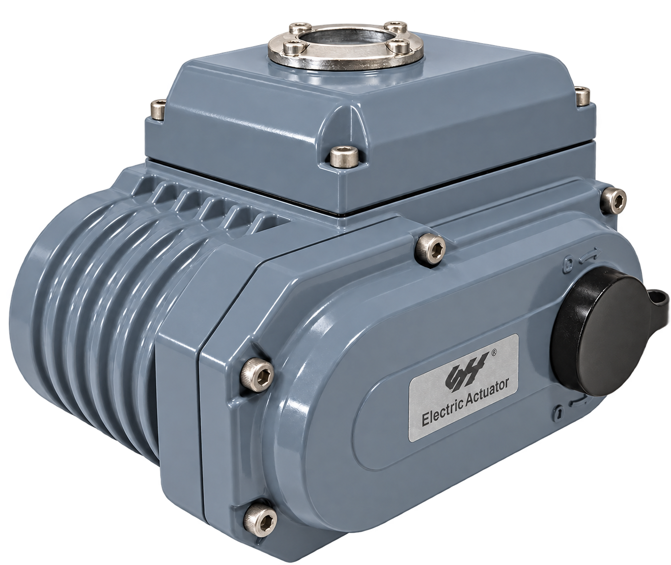
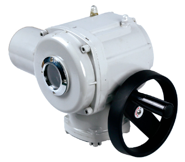
Compare the compact part-turn actuator and industrial part-turn actuator arrangements, or browse part-turn electric actuators. For an introduction to the drive and feedback system, read electric valve actuator working principle and types.
Send Actuator Details and Symptom Trends
General technical background: Emerson’s Control Valve Handbook discusses valve behavior and control terminology. Use the instructions and wiring documents for the installed actuator when planning checks.