
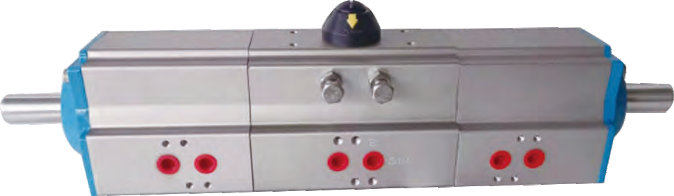
 Representative configuration
Pneumatic Actuators
Three-Position Pneumatic Actuator
A three-position pneumatic actuator provides two end positions and a mechanically controlled intermediate position.
View Product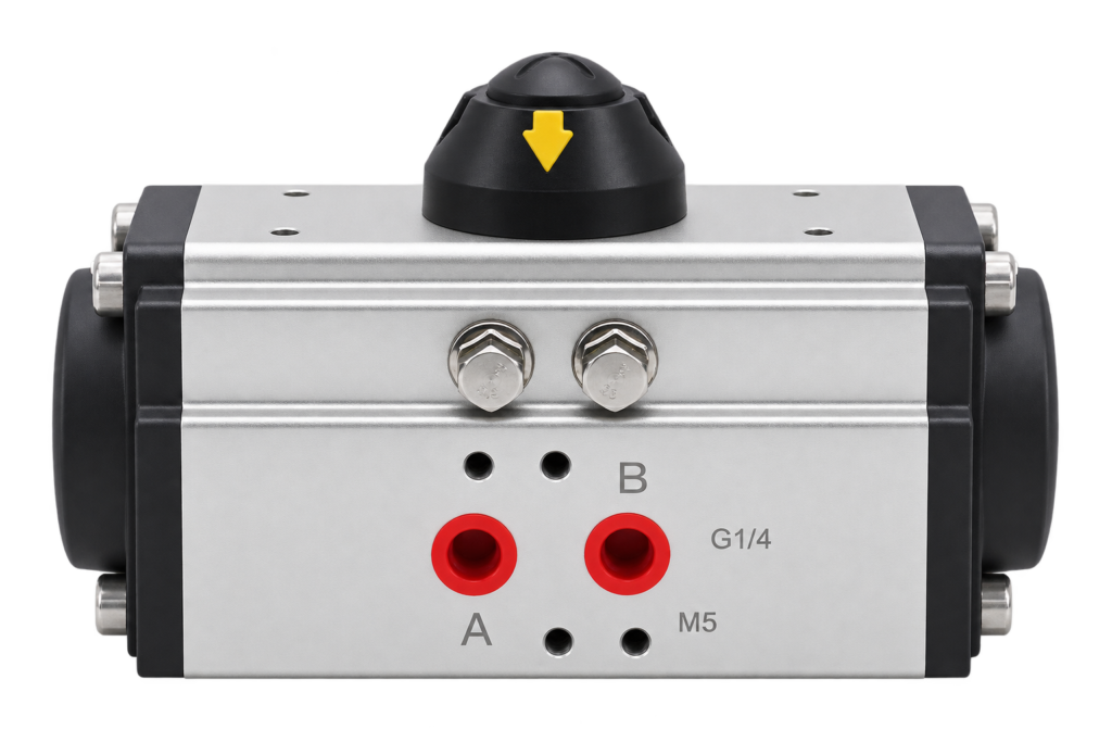
Representative configuration. Confirm the appearance and dimensions of the proposed model.
Compressed-air rotary actuation using a rack-and-pinion mechanism. Review valve torque, minimum available air pressure, required travel and loss-of-air response for the proposed assembly.
Send your requirements for the proposed configuration.
A rack-and-pinion pneumatic actuator converts the linear movement of air-driven pistons into rotation of an output shaft. This provides a drive arrangement for rotary valve applications. Selection begins with the valve's load profile and the air supply available at the actuator during operation.
The pressure measured at a compressor does not necessarily represent the minimum pressure at the actuator while the valve is moving. Air lines, control equipment and other demand on the system affect the supply. Provide the expected pressure range at the installation and request the corresponding actuator torque data.
Double-acting arrangements use compressed air to drive movement in both directions. Spring-return arrangements combine an air stroke with a spring-driven return stroke. Their output characteristics differ, so the valve load must be checked through the relevant movements. The presence of a spring-return actuator alone does not verify the behaviour of the complete control circuit.
State whether the valve must open, close or remain in a defined position following loss of air or command signal. Ask for confirmation of the proposed actuator arrangement and its accessories rather than assuming a failure position from the product photograph.
A solenoid valve can control air routing; position indication provides valve-status information; a positioner may be needed for intermediate positioning. Define the control objective, available electrical signals and feedback requirements so the appropriate arrangement can be reviewed. These components and their ratings are configuration-specific.
Provide the valve mounting pattern, shaft dimensions, coupling details and installation clearance. For a complete assembly, include the medium, valve size, connection, pressure and temperature. Request the actuator torque data at the specified pressure, dimensions and applicable air-circuit information before ordering.
Compare electric and pneumatic actuation, review the sizing checklist, or browse pneumatic actuators. Confirm final ratings and options against the datasheet for the selected configuration.
| Arrangement | Driving method | Selection consideration |
|---|---|---|
| Double-acting | Compressed air drives both directions. | Check torque at the minimum available pressure in both travel directions. |
| Spring-return | Compressed air drives one stroke; springs drive the return. | Check both air-stroke and spring-stroke torque and the intended loss-of-air response. |
| Three-position | A dedicated arrangement provides an intermediate stop. | Specify the complete stop sequence; ordinary end stops do not create a three-position actuator. |
Reference rotary travel arrangements include 90°, 120° and 180° versions, subject to the selected size and mechanism. For a dedicated intermediate-stop requirement, review the three-position pneumatic actuator.
| Seal option | Reference actuator seal temperature range |
|---|---|
| NBR | −20 to +80 °C |
| FKM | −15 to +150 °C |
| Silicone | −40 to +80 °C |
Specify ambient conditions, air quality and required service temperature. Confirm lubricant, accessory and valve limits as well as the actuator seals; the lowest applicable assembly limit governs.
Need mounting dimensions? Request the drawing for your proposed configuration.
| Mechanism | Rack-and-pinion rotary actuation |
|---|---|
| Operating arrangements | Double-acting or spring-return |
| Reference travel options | 90°, 120° or 180°, version dependent |
| Sizing input | Valve load and minimum pressure at the actuator |
| Seal options | NBR, FKM or silicone, selected for the operating conditions |
| Control accessories | Matched solenoid valve, limit switch box or positioner |
| Fail response | Define and confirm the complete actuator and control circuit |
Confirm the final ratings and dimensions against the documentation for your selected model.
Request the current datasheet, dimensional drawing and wiring or air-circuit information for the proposed product or assembly. Include your valve type and supply requirements so the documents match the configuration under discussion.
Representative configurationA three-position pneumatic actuator provides two end positions and a mechanically controlled intermediate position.
View ProductInclude the valve type, operating load, supply and control requirements.
Send your valve details and operating conditions to SHE.