Electric actuation for multi-turn valve movement
A multi-turn electric actuator drives a valve through more than one output revolution. Gate and globe valve installations often use this type of movement. The actuator, stem connection and any gearbox or thrust unit must be considered together: a suitable motor alone does not establish compatibility with the valve.
Separate torque, thrust and travel
Torque is the turning load at the drive connection. Thrust is the axial load associated with movement of the valve stem. Which loads the actuator or associated components must carry depends on the valve arrangement. Provide the valve manufacturer's load data and identify whether the stem rises during operation.
- Include required torque or thrust across the valve's travel.
- Record the stem diameter, thread details and mounting dimensions.
- State total travel or the number of output turns needed to fully open and close.
- Identify any existing gearbox, thrust unit or connection parts that must be retained.
Relate operating time to output speed
Required operating time depends on the number of turns as well as output speed. Send both values when known, together with the expected number of starts and operating cycles. Frequent positioning can impose a different duty from occasional isolation, even when the valve size and maximum load remain the same.
Confirm control and installation requirements
Specify the power supply, command signal, end-position indication and any continuous position feedback. Describe local and remote operation needs and the required response to loss of power or signal. Communication interfaces, enclosure protection and hazardous-area suitability must be verified for the chosen configuration.
Check that the installation leaves room for stem movement, cable entry, maintenance and any specified manual controls. The commissioning procedure must establish the appropriate travel limits and torque settings for the valve; do not copy settings from an unrelated installation.
Information for a replacement or new installation
For replacement work, send the existing valve and actuator identification, mounting drawing and available wiring information. For a new assembly, add the medium, pressure, temperature and connection details. Mark unknown values clearly so they can be addressed during selection.
Use the valve actuator sizing guide and control-duty comparison, or browse multi-turn electric actuators. Confirm the final datasheet, dimensions and wiring for the proposed model before ordering.
Side-handwheel reference range
The illustrated side-handwheel construction provides manual access beside the actuator, leaving the top area available for the enclosure and controls. Nominal torque changes with the selected size and output speed; the following paired values belong to separate speed configurations.
Side-handwheel family reference. Each row is a different actuator size; compare output torque at the stated speed.
| Nominal torque at 24 r/min (Nm) |
Nominal torque at 48 r/min (Nm) |
| 100 |
60 |
| 150 |
90 |
| 200 |
120 |
| 300 |
180 |
| 450 |
270 |
| 600 |
480 |
| 900 |
540 |
| 1000 |
600 |
| 1200 |
720 |
| 1800 |
1200 |
| 2500 |
1700 |
| 4500 |
3000 |
Specify total turns and target operating time along with torque or thrust. Handwheel position, stem clearance, power supply and control package must be checked on the proposed assembly drawing. A smaller top-handwheel arrangement is available as a separate compact multi-turn product family.

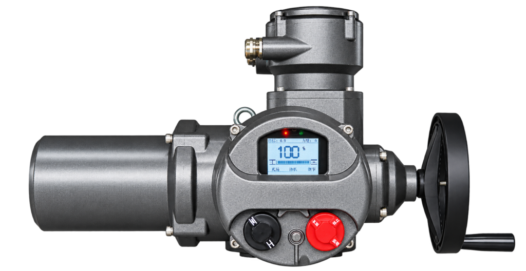
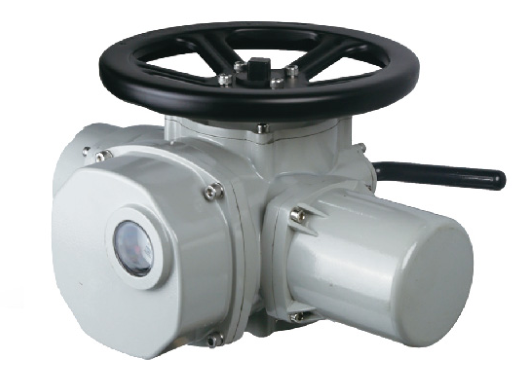 Representative configuration