
Electric Valve Actuators: Working Principle, Types and Troubleshooting
Learn the electric valve actuator working principle, compare motion and control types, and use a fault checklist to prepare your application enquiry.
Published by SHE · 16 October 2026 · Electric valve actuator fundamentals
An electric valve actuator converts electrical power into the movement needed to open, close or position a valve. A motor drives a transmission, while the selected controls manage direction, stopping and any required position feedback. In a modulating configuration, an internal position controller compares demand with measured position and drives the mechanism to reduce the difference.
In process-control terminology, the complete final control element can include both the actuator and the valve. In a product enquiry, however, “actuator” often means the drive unit alone. State whether you need a bare actuator, an actuator with mounting components or a complete actuated valve assembly so that the supply scope is clear.
1. Classify the actuator by energy, motion and control
Actuators can use electric, pneumatic or hydraulic power. That energy-source classification does not describe the required output movement or the controller interface. A useful specification records all three separately: available power, mechanical motion and the way the actuator is commanded.
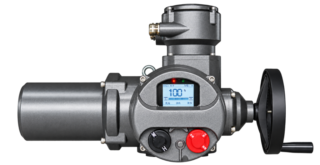
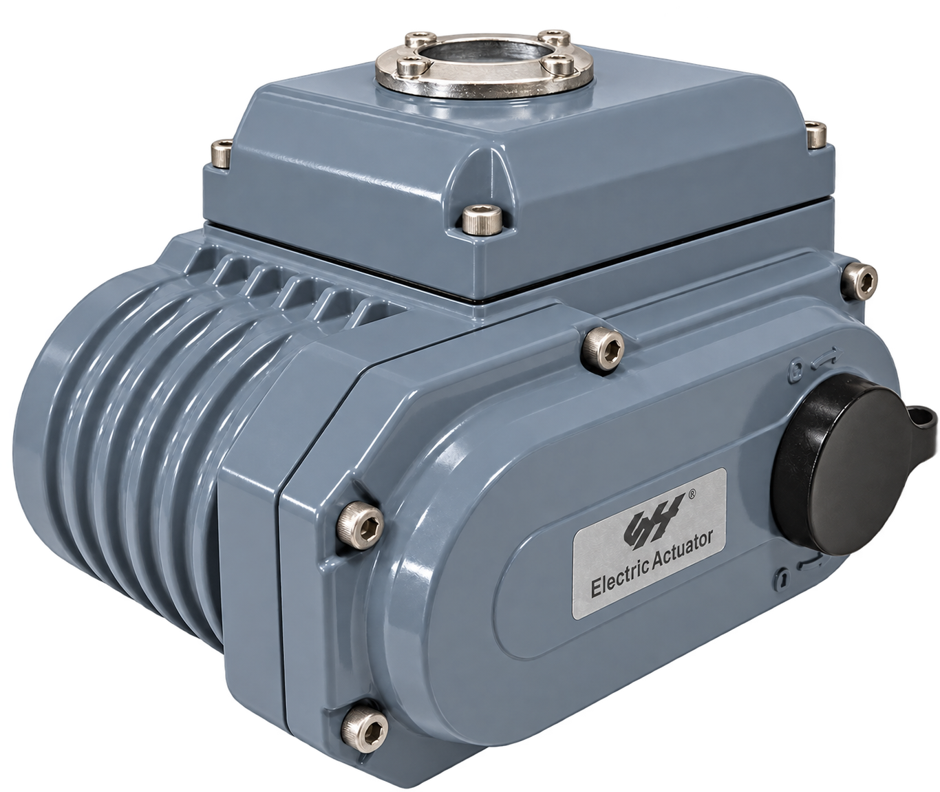
Part-turn actuators provide a limited angle of rotary travel and are commonly considered for compatible ball valves, butterfly valves and dampers. Multi-turn actuators provide several output revolutions and are often considered for gate or globe valve arrangements. Linear movement may be provided by a dedicated linear mechanism or by a suitable rotary drive and thrust arrangement.
| Classification | Typical distinction | Information to provide |
|---|---|---|
| Drive energy | Electric, pneumatic or hydraulic. | Available supply and required response to supply loss. |
| Output motion | Part-turn, multi-turn or linear. | Travel angle, number of turns or stroke, with load information. |
| Control duty | On-off, intermediate positioning or repeated modulating duty. | Operating frequency, movement time and required positioning behavior. |
| Command interface | Contacts, analogue demand, pulses or a supported communication interface. | Exact signal type, range and control logic. |
| Feedback | End-position contacts, continuous position or other specified status. | Required output, receiving system and diagnostic information. |
Some terminology describes control algorithms rather than a separate actuator construction. In particular, an actuator receiving a continuous position demand is not automatically a process PID controller. Read on-off versus modulating control before choosing the operating duty.
2. Follow the position-control loop
Consider a modulating actuator configured for an analogue position command. The internal controller receives a demand representing the desired position. A position sensor measures the actual output position. The controller compares the two and commands movement in the appropriate direction until the difference falls within its configured stopping criteria.
- The process controller determines the required actuator position from the process objective.
- The actuator receives the specified demand, such as a supported 4–20 mA position signal.
- Its position-control system compares demand with measured output position.
- The motor and transmission move the output to reduce the position difference.
- The controller stops the drive according to the applicable position, travel and protection settings.
- The configured feedback reports position or status to the receiving system.
This is an explanation of the signal path, not a universal wiring diagram. An on-off version may use separate open and close commands instead of continuous analogue positioning. The command input, position sensor and feedback output can also differ between control packages.
The outer process loop and the inner positioning loop serve different purposes. The process loop regulates flow, pressure, temperature or another measured variable. The positioning loop moves the actuator toward its demand. Understanding the distinction helps explain why a drive can follow its command correctly while the overall process still oscillates.
3. Understand the main components
| Element | Function | Configuration check |
|---|---|---|
| Motor | Supplies the mechanical driving energy. | Supply, motor duty, operating time and applicable thermal protection. |
| Transmission | Converts motor movement to the required output speed and load. | Gear arrangement, output connection, torque and any thrust requirement. |
| Motor controls | Manage direction, starting and stopping. | Controller type, command interface and any model-specific stopping or braking system. |
| Position sensing | Measures output movement for indication or control. | Sensor technology, calibration and feedback signal. |
| Travel and load protection | Provide the applicable limits and protective functions. | Valve-specific settings and the intended stopping method in each direction. |
| Manual operation | Provides local operation where the design includes it. | Engagement method, access and restrictions during powered operation. |
Do not transfer a thermostat temperature, terminal number, amplifier-board designation or reset method from an unrelated actuator. Some designs use mechanical switches and potentiometers; others use different sensing and electronic arrangements. A component list explains functions without establishing interchangeable parts.
Likewise, a reduction gearbox does not automatically guarantee a specified holding capability or failure position. Confirm the complete drive arrangement and the required response after loss of power or command. Manual-operation instructions and travel-limit settings must also belong to the installed model and valve.
4. Match the actuator to the application
Begin with the valve load across its travel. For rotary arrangements, obtain starting, running and seating torque. Where linear stem movement is involved, identify thrust, stem details and which assembly components carry the axial load. Nominal pipe size or motor power alone does not provide that information.
Next specify movement and operating time. A part-turn enquiry needs the required travel angle. A multi-turn enquiry needs total turns and output speed or target travel time. A linear arrangement needs stroke and the appropriate motion conversion. Check mounting pattern, shaft or stem dimensions, coupling engagement and installation clearance.
Define the expected duty: occasional isolation and frequent positioning can impose different demands. Record starts or movements per hour, typical movement duration, ambient conditions and the control objective. Ask for the selected unit’s applicable duty information rather than assuming that any electrically driven actuator can perform continuous modulation.
Electrical power is readily available at many installations, and electric control can integrate conveniently with remote systems. Those benefits still depend on the actual power distribution, command interface and control package. Compare the complete installation with electric and pneumatic actuation options where both are being considered.
Environmental suitability is configuration-specific. Electric actuators are not categorically excluded from hazardous areas, but a general-purpose unit must not be assumed suitable. Specify the area requirements and request applicable certification and installation documentation for the exact proposal. Enclosure protection, corrosion resistance and explosion protection are separate checks.
5. Use symptoms to organize fault checks
A symptom identifies a starting point, not a confirmed failed component. Establish the actuator model, control version, operating mode and fault indications before inspecting parts. Electrical testing and mechanical intervention should follow the manufacturer’s instructions and the site’s isolation procedure; do not bypass protective devices to make the motor run.
| Observed symptom | Areas to investigate | Evidence to collect |
|---|---|---|
| Motor does not run and is silent | Supply, selected mode, command path, permissives, protective trips and motor controls. | Mode indication, demand, alarms and the model-specific connection information. |
| Motor hums without useful movement | Mechanical obstruction, drive condition or electrical supply and motor fault. | Supply conditions, valve load, indication and the circumstances of the failed start. |
| Motor chatters or repeatedly starts | Unstable demand, control or switching fault, feedback instability and load behavior. | Time-aligned command, position, process and fault records. |
| Drive moves but remote position is absent | Feedback selection, sensor connection, output circuit and receiving system. | Actual valve movement, local indication and the expected feedback type. |
| Position feedback remains fixed | Sensor or drive connection, signal path, configuration or receiving-channel problem. | Local and remote readings over a permitted movement, with wiring identification. |
A failed starting capacitor is relevant only to a motor arrangement that uses one. Similarly, a faulty potentiometer or solid-state relay is one possible model-specific explanation, not a diagnosis for every silent, humming or chattering actuator. Confirm the circuit before selecting replacement parts.
If the mechanism moves normally but the remote position stays fixed, compare local position, independently observed valve travel and the received feedback. Check the required signal range and direction as well as the connection. Replacing an actuator will not correct a receiving-channel configuration error.
For repeated cycling around a demanded position, use the separate six-cause electric actuator hunting guide. It distinguishes measurement fluctuation, PID behavior, valve gain, mechanical problems, interference and local positioning faults.
6. Choose useful monitoring and control options
Evaluate display, local controls, continuous feedback, communication interfaces and diagnostic functions according to the operating need. Ask what information each option provides, how it is accessed and how it integrates with the control system. A product appearance or the word “intelligent” does not confirm a particular protocol or diagnostic capability.
For maintenance planning, request the applicable operating instructions, fault definitions and configuration record. Confirm which settings can be read, which require authorization to change, and how the final configuration will be documented. These practical requirements are more useful than unsupported claims about universal reliability or maintenance-free operation.
7. Prepare the information for an actuator enquiry
Send the valve identification, medium, pressure, temperature, load data, required movement and operating time. Add the supply, duty, command, feedback, failure-response requirement, mounting drawing and installation environment. For replacement work, include existing actuator details and the relevant wiring documentation.
Use the valve actuator sizing checklist to identify missing information. Compare SHE’s part-turn electric actuator and multi-turn electric actuator families by motion and installation requirements. Confirm the proposed configuration’s datasheet and drawings before ordering.
Send Your Valve and Control Requirements
General manufacturer documentation illustrates why configuration matters: AUMA provides product-specific wiring diagrams, and Rotork’s IQ3 documentation separates installation, configuration and technical information. These references do not establish SHE product ratings or interchangeable wiring.